Digital Card Model’s Sopwith Wright
A Review By Mark A. Johnson
Photographs by Mark Johnson
Background:
After their initial flights in 1903 the Wrights returned to Dayton, Ohio and mastered the art of flying with two new machines in 1904 and 1905. The 1904 airplane was a near duplicate of the 1903 Flyer. One change they did make was to move the center of gravity to the rear a few inches. With this small change they unwittingly decreased the pitch stability of an already unstable airplane. The 1904 airplane therefore proved extremely difficult to control and left them quite discouraged. For the 1905 airplane they increased the elevator size and moved the cg forward. These changes gave greater pitch control along with improved stability and this became the world’s first practical airplane. In 1905 the Wrights could remain a loft for long periods (The longest flight during 1905 was 38 minutes) and achieved complete control over the machine.At the end of the 1905, confident that they had fully uncovered the secrets of flight and concerned that further public testing would jeopardize their secrets, they stopped flying for nearly three years. Some believe this delay hurt the Wright’s ultimate ability to capitalize on their invention. During the three years from 1905 to 1908 other inventors also managed to fly although their best efforts more closely resembled the Wrights’ 1903 flights. Significant among these aviation pioneers was Santos Domont, a Brazilian, who first flew his 14-Bis publicly in France in October of 1906. Although his flight was only a few hundred feet in a straight line, (while the Wrights were flying circles for over half an hour a year earlier), he performed in full public view of large crowds. The Wrights’ relative secrecy caused most of the world to doubt that they had flown at all.
Then on Aug 8, 1908, Wilbur Wright publicly demonstrated the Model A during a tour of France. The stunned crowds where expecting to see at best more of the short hops they’d been accustomed to seeing. Imagine their surprise to see Wilbur in complete control of his highly maneuverable airplane, flying as long as his fuel would last. This 1908 Model A Flyer proved to the world that the Wright brothers had indeed mastered the air.
During military trials at Ft Meyer in Virginia later that year Orville crashed while flying another Model A, killing his passenger, Lt Selfridge. Analysis showed that a propeller had shifted, severing a wire and leading to catastrophic structural failure. Orville escaped with a few broken bones.
After further successful testing the Wrights where awarded a contract for two "Military Flyers", which were delivered in 1909. One of these original Military flyers is on display at the Smithsonian’s National Air & Space museum alongside the 1903 Flyer.
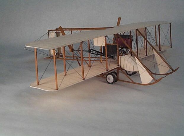
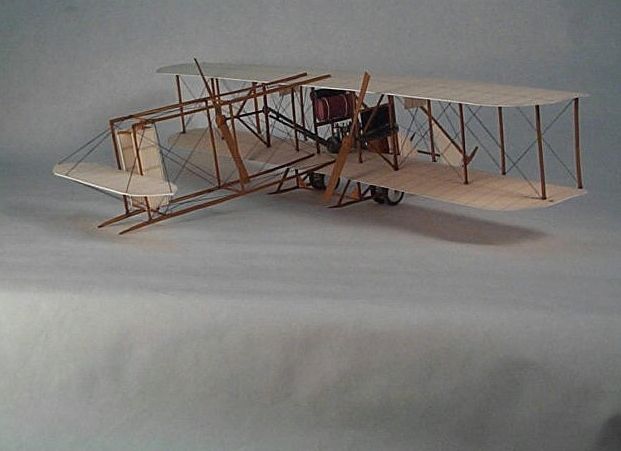
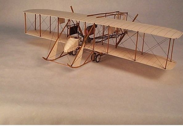
The next machine, Model B, was the world’s first mass-produced airplane. During his tour of Europe in 1908, Wilbur experimented with moving the elevator from the front to the rear of the airplane. This was the primary change included in the Model B. This airplane was produced under license in the US and Europe. Tommy Sopwith acquired one of these European machines sometime around 1911 and it is his "Improved" airplane that is replicated in this kit.
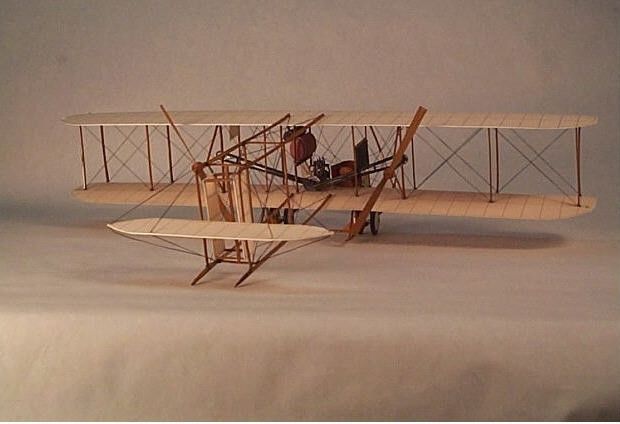
The changes Sopwith made to the standard Model B appear to include reducing the seats to one, adding a fairing to protect the pilot from the wind, reversing the engine and seat locations, and moving the engine and seat closer to the center of the airplane. The Sopwith version also has a different radiator than other B models. When you compare early photographs of these airplanes you realize that no two of them are alike. There are many small variations from airplane to airplane and therefore we can’t be sure how many of these changes where Sopwith’s.
This model could easily be built as a standard Model B by relocating the components, adding a second seat, and scratch building the simple pilot’s control structure.
You could also create an A-Model but this would require considerable rework including a new structure for the front mounted elevator. Another interesting variant would be the shorter winged, single seat Model EX (EX stood for Exhibition). Cal Rodgers flew an EX named the Vin Fiz on the first transcontinental flight in 1911.
The Model:
The kit is provided digitally for you to print on your own color printer. The first things you notice on examining the parts sheets are the many delicate struts that must be laminated and carefully trimmed. Here is how I handled this rather daunting task.There are many struts on this model. You can mass-produce these to save time and ensure uniformity. Glue up a stack of three cards with width the same as the length of a strut. Make the cards long enough so you can get all you need from one stack. Dry this under a heavy weight to make sure it’s perfectly flat. Mark off the width of the struts on both edges of the stock. Slice off the struts, round the edges slightly with sandpaper, and paint light brown or tan (I use Testors flat brown). If you’re a purist, note that the struts on the prototype taper toward the ends. I did not add this detail on my model.
Assembly: Here is an easy and reliable method for assembling biplane wings on card models. Using tacky glue, attach all the struts to one half of the assembly (i.e., the lower wing). Try to get these as perpendicular as possible. The glue will set quickly and usually needs no extra support. When dry, turn the assembly upside down on the opposite part (i.e., the upper wing). Glue the struts one at a time, allowing the glue to set before moving on to the next attachment. Any misalignments will normally work themselves out as you proceed. When the entire assembly is dry, gently push it into final alignment, if necessary. Use this procedure to also assemble the tail truss and the landing gear truss.
I think I got close to the right thickness and shape by gluing the trailing edge only, pressing the top and bottom flat together, and letting the natural tendency to spring back give the wing a bit of thickness. To curve the wings I use a 1/8 inch thick rubber mat I found at a craft store. These mats come in many bright colors and sell for less than 1 dollar each. In the same area of the store you often find a bag of assorted diameter wood dowels. I use a 3/8 inch dowel to roll in the curve on most wings. Simply place the part on the mat and roll the dowel over it. Be sure the dowel you use is smooth. I often need to sand these before use so they don't crease the part.
Engine:
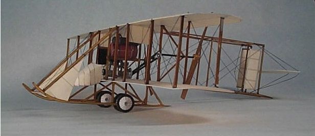
A good basic Wright 4 cylinder engine is provided in the kit. The engine is highly visible in this airplane and a few hours of detailing make a big difference. After assembly, I painted the entire engine with Testors silver. When dry, I gave it a thin black wash to make it look like steel. You can then pick out a few details in flat black. I added one #26 gauge florist wire pushrod alongside each cylinder. (This was for the exhaust valve, the intake valve was opened by the suction that the piston created during the intake stroke). On top of each cylinder are the two valves. You can simulate these with small paper rectangles, painted black or silver. On the starboard side of the engine is a cooling pipe that crosses all the cylinders then bends down at a 90-degree angle in front of the engine and is connected to the water pump. Just before the bend is a short rubber hose that splits the pipe in two. Make the pipe from 18-gauge florist wire and the hose from a bit of masking tape painted black. I used a spare propeller sprocket glued to the front to add a little interest and simulate the water pump. On the port side is the carburetor and intake manifold. I made these from rolled paper, bent into shape and painted steel and silver. There are more details you could add including the electrical system, but this level of detail seems about right on my model.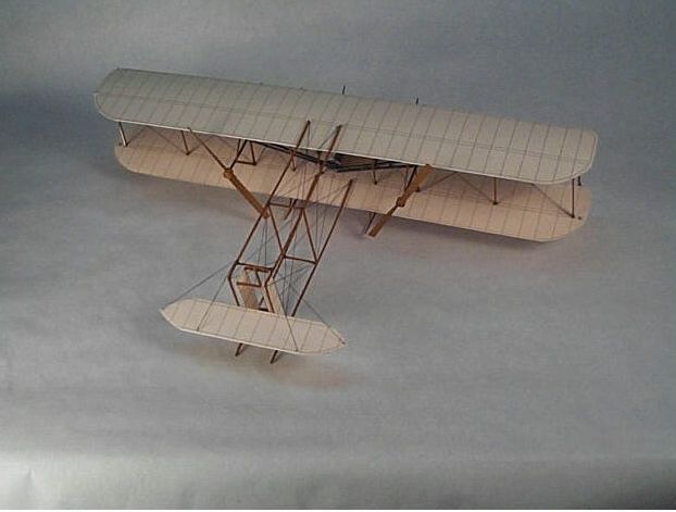
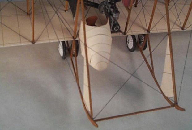
Undercarriage:
There are four wheels attached to two small axles, suspended just above the skids with bungee cable. The kit supplies paper parts for these axles, but I used 18-gauge wire. The wheels are built up card laminations with paper cone disks to represent the spokes. This model would be a great application for wire wheels if you have a technique you like. After trimming and sanding, I painted the tires a very dark gray. After adding the spoke cones, I drilled the center holes for mounting to the axles. The axles themselves were first glued in place, then lashed with thread to give strength and to simulate the original attachment.Accessories:
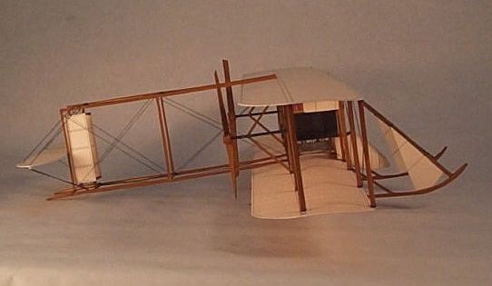
The kit includes several additional pieces including two tanks (Fuel & ?), a pilot fairing, propellers, a seat, and various aerodynamic pieces. The most difficult assembly of the entire project is the fairing. This structure is built up from many small strips but there are no connecting strips provided. To make your own, trace along the edge to be joined on the smaller of the two parts. Connect the strip to the smaller part after forming and when dry, fit the two parts together. The fit on this assembly is very good and it yields a rather crude looking fairing which mirrors well the crude fairing Sopwith devised.The two very good looking and well-designed tanks are formed into cylinders, the ends covered with rounded caps. A pair of straps wrap around each tank to add detail and provide mounting points.
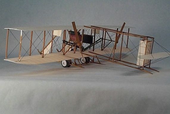
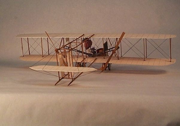
Final Assembly:
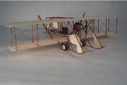
With the wings, undercarriage, and tail completed as subassemblies, I attached the tail to the wings, then the wings to the undercarriage. I chose to rig the model with black thread although it is an impressive model even unrigged. I use a simple method where the thread is tied in an overhand knot around the base of each spar. After adjusting and tightening a drop of glue (thin CYA works best) is applied to set the knot before moving to the next location. There are very many wires on this model, some for structure, some for control. Don’t feel like you must install them all, just keep adding until it looks good to you.Summary: This kit took a bit longer than most of my projects but went together with very few problems. The paper gives the parts a handmade look that reflects well the handcrafted original. If you are willing to think through the gaps in the instructions, this kit will reward you with a fine little piece of history.
ã
2001, Mark A. JohnsonSummary Table for Digital Card Model’s Sopwith Wright
|
Model: |
Wright Model B, modified by Tomas Sopwith |
|
Kit: |
Digital Card Models ( http://ww1cardmodels.bizland.com/)Available from - www.ww1fighters.com/go_dcmstore.htm |
|
Designers: |
Gabrial Panait, and Steve Bucher |
|
Scale: |
1:32 |
|
Difficulty |
Difficult – 7 (See Card Model Grading Scale at the end of this document) |
|
Number of Parts: |
Appx. 150 |
|
Time Required: |
36 |
|
Instructions: |
None Provided |
|
Diagrams: |
Period Photo and a Fair three view drawing |
|
Fit: |
Excellent |
|
Coloring and Artwork: |
Very Good: Produced with vector graphics. Provides unlimited scaling potential but limits weathering and shading. |
|
Printing: |
User Printed. As good as your printer |
|
Resources: |
Search the web for Wright Model B. Some sites I found useful are: http://www.first-to-fly.com/History/wright1.htm, http://www.nasm.edu/nasm/aero/aircraft/wrightex.htm http://www.wpafb.af.mil/museum/early_years/ey1.htm http://www.wpafb.af.mil/museum/early_years/ey2.htm If you can find it, Model Airplane News published a book with detailed drawings of WWI aircraft. This book includes the Wright Model B. Both NASM and the Air Force museum have examples of similar aircraft. |
|
Credits: |
Bill Geoghegan for inspiring this review format. |
|
Tool & Materials: |
Exacto Knife with sharp #11 blades Very Dull #11 blade for scoring (dull it with a file & test to be sure) Small Scissors Fine Black Cotton Thread Straight Edge Cutting Mat (Optional) Light Flat Brown, Flat Black, & Silver Enamel Model Paint & Enamel Thinner Medium Pointed Brush #26 & #18 Gauge Soft Wire (Sold as florist wire. Look for the straight package 1/8, & 3/8 in dowels for shaping parts 12x12 in soft rubber mat Fine sandpaper Tweezers "Tacky" Glue Toothpicks Glue Dispenser(Optional) Super Glue (Optional) |